
Astha Infra Engg Pvt LTD(I)
Jump Slip Form Equipment,Manufacturer,Supplier And Exporter
Astha Infra Engg Pvt LTD(I)
Slip Form Equipment,Manufacturer,Supplier And Exporter


Concrete pump may be used in construction of silo wall by slip form. As the concrete pump has accelerated the rate of concreting, so much faster progress we can expect. By this process of concreting we can reduce the manpower engagement. Concreting by concrete pump in slip form work give us the better quality of concrete by reducing the handling of concrete in different stage. As the pouring time incase of using concrete pump is less so we can pour s complete & uniform layer well before the initial setting time of concrete. And this practice gives us smooth surface of wall. Concrete pouring in uniform layer well before the initial setting time of concrete has helps in uniform lifting of the slip form so we can able get better reading with the plumbs. By the above discussion it is clear that concreting by slip form work gives us lot more control in quality of concrete, accurate plumb of the structure and better surface of concrete wall. Not only that it's much economical process to get exact technical specification required in the actual operation of the structures, as the engagement of labour is less & the progress of work is faster.

We are an eminent EPC (Engineering Procurement and Construction) contractor of cement, flyash& clinker silo. The offered range is designed using high quality raw material and the most advanced technology under the supervision of skilled professionals. Further, we constantly keep track of the latest industry developments in order to maintain the quality of products. These are available in different sizes and design specifications to meet the exact demands of our customers. A silo is a structure for storing bulk materials. Silos are more commonly used for bulk storage of grain, coal, cement, carbon black, woodchips, food products and sawdust. Three types of silos are tower silos, bunker silos and bag silos. There are different types of cement silo / Fly Silosuch as the low-level mobile silo and the static upright cement silo, which are used to hold and discharge cement and other powder materials such as PFA. The Cement low-level silos are fully mobile with capacities from 10 to 75 tons. They are simple to transport and are easy to set up on site. These mobile silos generally come equipped with an electronic weighing system with digital display and printer. This allows any quantity of cement or powder discharged from the silo to be controlled and also provides an accurate indication of what remains inside the silo. The static upright silos have capacities from 20 to 80 tons. These are considered a low-maintenance option for the storage of cement or other powders. Cement silos can be used in conjunction with bin-fed batching plants.
We have cutting edge technology that allows us in offering Construction Service for Cement Silos / Fly Silos . These storage silos are fabricated using high grade material of construction and are stringently checked on well defined parameters. Widely used for high grade coatings, these are provided in two different configuration such as skirted silo or spread-leg silo as per the requirement.


In RCC Cement Silos / Fly Silos construction,the formwork involves considerable material and labour costs and involves time. Thus the overall cost depends significantly on the formwork. It is very pronounced in the case of structures of large heights. The engineers and contractors always strive to rationalize the formwork to the extent possible. For many cases slip form is considered the right solution for these task.
We Offer Cement Silo with following features:
1.Rugged construction
2.Easy installation
3.Longer service life
4.Minimum maintenance
5.Cement silo fluidized system
6.Screw conveyor
7.Cement silo filter system
8.Seamless pipe for feeding material in silo.
9.With safety guards, pressure switch, Non return Valve and pressure gauge and pressure safety valve.
We are an organization engaged in offering various types of Cooling Tower Construction services. We have in-depth domain knowledge, facilities and workforce to undertake these construction services effectively. Premium grade material is used in the construction process while adhering to the industry standards. The construction services are cost effective and timely completed to meet the growing demands of clients. The construction services are cost effective and timely completed to meet the growing demands of clients. Construction Services for Cooling towers Cooling towers are heat removal devices used to transfer process waste heat to the atmosphere. Cooling towers may either use the evaporation of water to remove process heat and cool the working fluid to near the wet-bulb air temperature or, in the case of closed circuit dry cooling towers, rely solely on air to cool the working fluid to near the dry-bulb air temperature.
We Offer construction services for Cooling towers with following features:
1. Reliability
2. Client centric
3. Timely completion
4. Adherence to industry standards
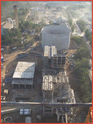
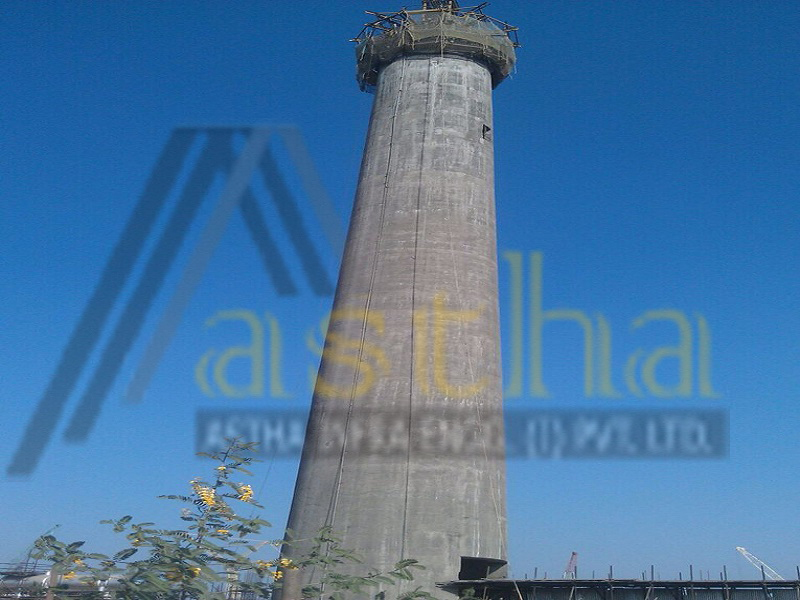
This is the photograph of Blending Silo after the completion of slip form work. Blending has the 15m diameter & 52m tall structure. Here concrete pump had used for concreting of the wall. We can see here the surface & alignment of wall is almost accurate. The average rate of lifting achieved in this construction 2.5m per day. So, the experiment of concreting by concrete pump in slip form work is successful. This experience has shown us a new way of working in slip form to achieve better quality of construction. It was constructed in phases. 1st up to +15m (wall thickness 800mm) has taken 8 days and 2nd from +15m to +52m has taken only 22days.
By the successful experiment of Blending Silo slip form work, we have construct the clinker silo by the same process of concreting and made it second time successful. Clinker Silo is the biggest silo in our Lafarge Sonadih Project. It has 45m diameter & 26m tall. We have used here 3 nos. of concrete pump for feed the concrete during slip form works. Total wall length had divided in to 3 parts and to feed the each area a concrete pump has engaged. We have also successful here by adopting this process of concreting in slip form. Duration taken in construction of clinker silo only 19 days.


In clinker silo we have used three nos. of concrete pump to feed the concrete into the wall during slip form work. Photographs are showing the concrete pump used during slip form work. Concrete pump showing in the photograph feed one-third portion of the silo wall.
Boom placer also being used to feed the concrete to feed another one-third portion of the silo wall. This photographs has been taken during slip for work of clinker silo. By the above process concrete feeding has done for concreting work at clinker silo.
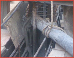

This photograph has taken during concreting was done at Clinker Silo. Here we can see the concrete has poured to slip form shutter through the hose pipe of concrete pump pipeline and this hose pipe has connected to main pipeline of concrete pump.
After successful completion of Blending & Reject Silo in this process of concreting, we have applying same process of construction another one no. of silo (Reject Silo). Reject Silo have 12.5m diameter & 35m tall. We have completed this silo wall by slip form only by 13 days with maintaining better quality of work & safety.
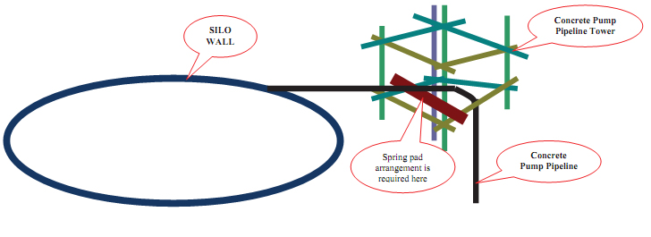
Precaution to be taken incase of Concreting by Pump in Slip form Works:
There is chance to disturb plumb of slip form during concreting concrete pump due to vibration produce by concrete pump during each stroke. To avoid this vibration we have to be use spring pad. During concreting work spring pad is to be placed under the concrete pump line near to the slip platform where the pipeline get bend. This can minimized the vibration produced by concrete pump.

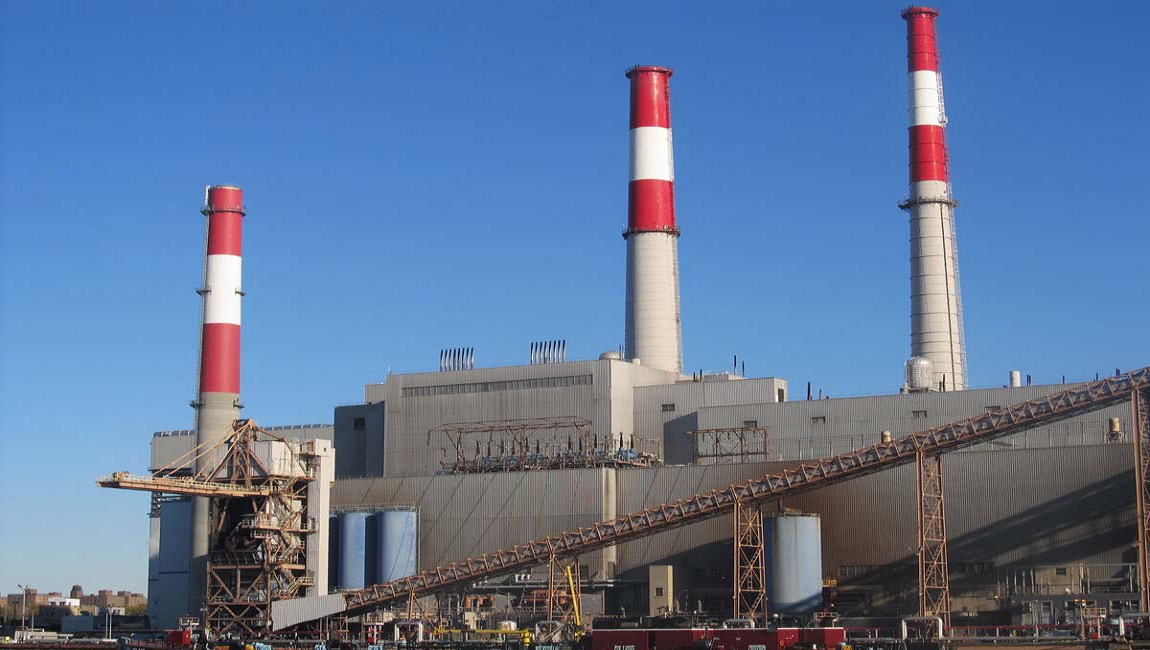
An industrial chimney is an arrangement for ventilation for hot flue gases or smoke from a boiler, stove, furnace or fireplace to the outside atmosphere. A industrial chimney / flue-gas stack is a type of chimney, a vertical pipe, channel or similar structure through which combustion product gases called flue gases are exhausted to the outside air. Flue gases are produced when coal, oil, natural gas, wood or any other fuel is combusted in an industrial furnace, a power plant's steam-generating boiler, or other large combustion device.. These types of industrial chimneys may be used in Power plant, Chemical plant, Cement plant, Hydro and gas plants
The height of industrial chimneys plays a role in their ability to transfer flue gases using stack effect, the dispersion of pollutants at higher altitude helps to ease down its influence on surroundings. In the case of chemically aggressive output, the tall industrial chimney allows partial or complete self-neutralization of chemicals in the air before they reach the ground. The dispersion of pollutants over greater area reduces their concentrations in compliance with regulatory limits.
we are specialization in manufacturing industrial chimneys for diverse industrial segments. We undertake designing, erection, manufacturing as well as executing work of industrial chimneys for providing all the solutions to the clients under one roof.
Construction Services for Chimneys :
Industrial chimneys are commonly referred to as flue gas stacks and are generally external structures, as opposed to those built into the wall of a building. They are generally located adjacent to a steam-generating boiler or industrial furnace and the gases are carried to them with ductwork. The use of reinforced concrete has almost entirely replaced brick as a structural component in the construction of industrial chimneys.
1. Bar Fixing Works Services
2. Drilling Works Services
3. Core Cutting Works Services
4. Slip Form Material Fabrication
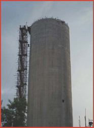
In RCC Chimney construction,the formwork involves considerable material and labour costs and involves time. Thus the overall cost depends significantly on the formwork. It is very pronounced in the case of structures of large heights. The engineers and contractors always strive to rationalize the formwork to the extent possible. For many cases slip form is considered the right solution for these task. The construction services we offer are RCC Chimney Construction and Chimney Contractor. Each chimney that we construct is designed as per the clients' needs and particular industry standards, ensuring complete safety of the erected setup.
Objective of this procedure is to provide a guideline for sequence of operations pertaining to Slip form Works for Silo Construction, so as to ensure that the works are carried out in a systematic manner and to ensure that the works conform to the Owner’s specification and drawings.
This procedure is applicable for Construction of Clinker Silo at Lafarge Sonadih Cement Plant.
This Procedure is based on the requirements of the Owner’s Technical Specification for Civil/Structural works for Silo package works and Simplex Experience in Construction of Silo by Slipform.
The Contractor shall deploy any or all of the following resources as dictated by the volume and nature of work.
a) Tools & tackles Spade. Shovel Basket Wheel Barrow Steel Wire Rope Spanner b) Plant & Machinery Batching Plant. Transit Mixer. Concrete Pump with pipeline. Builder Hoist Winch. High Frequency Vibrator with Needle High lift curing pump. Boom Placer. In addition to the above, the Contractor shall deploy a specialist agency for slip forming having experience for carrying out such work.
We propose that we shall erect the slipform shuttering right from F.F.L. of R.C.C. Shell of Outer Wall. The shuttering plates and other various components of Interform type slipform equipment shall be erected as per line and level required for Clinker Silo. The jack rod for 6 / 3 T Hydraulic Jacks shall rest on steel shoe placed at the top of already cast shell.
Some of the salient features of the various components to be used for the slipform technique as shown in SKETCH NO.: 012 / DD / LAFARGE S / SILO / SDS / 002 Rev – 0 are explained below.
5.1 Yokes: A set of yoke leg placed at required alignment and connected by means of yoke beams at the top wherein climbing jack mounted, provides key members for fixing the Form Panel for inner and outer faces. Requirements of total number of yoke sets depend on the sizes of the structure and the capacity of hydraulic jack. Spacing of the jack would be around 1.25 m for this Clinker Silo.
5.2 Slipform Hydraulic Jacks: We shall be using 75 nos. 6 T capacities “Interform” type hydraulic jacks which climbs on bright steel rod of 32 mm dia and operates with two sets of ball grip. Jacks can only move upward direction when hydraulic pressure is applied. The upper movement of the slipform will be as per set criteria provided by the manufacturers of the Jacks or minimum of 100 mm / 150 mm per hour.
5.3 Consoles: Consoles shall be provided on to the yokes meant for support of the working platform both inside and outside. This working platform shall be used for concreting, reinforcement binding and operation of the hydraulic pumps. Consoles will be fabricated members in combination with structural angles and tubular pipes / reinforcement rod with structural channel, angles & tubular pipes.
5.4 Hanging Scaffolding: These members are suspended from consoles both inside and outside for the purpose of inspection and finishing work of the exposed concrete after slipping. These hanging scaffolds will be of rigid frame structural members.
5.5 Waler: These member spans within the two yokes and provide support for the Form Panel against Lateral Force due to green concrete.
6. Support For Reinforcement Steel: Arrangements made from the top of yoke beams with reinforcement guide, supports reinforcement to maintain its aligned position.
7. Guard Railings: For the safety arrangement guard railings with post placed at the working platform both inside and outside and reinforcement type rails also provided for the hanging scaffolds.
8. High Pressure Hydraulic Pumps Pipelines & Fittings: Circuit oil lines of high-pressure rubber hoses inter-connect all vertical jacks and plug in unit with one or more centrally positioned electrically powered high-pressure pump. Connections to the jacks and pump are carried out through valves and male and female fittings ‘as required’.
9. Illumination: Illumination is essentially required as the work normally carried out 24 hours a day non- stop. Accordingly both on working platform, at the hanging scaffolds, stairways and working areas are illuminated properly.
10. Operation: For smooth operation of slipform, jack readings and plumb readings are to be monitored once in every two hours.
11. Access Tower: Access tower is to be installed for concrete lifting and climbing of personnel through temporary stairs, made of ISMC &ISA..
12. Special Arrangements: 1. Minimum 10% extra jacks are required as standby. Adequate jack rods should also be available at site.
2. 75 nos jack of 6 T capacity each to be put on the job i.e. with a spacing of around 1.25 m c/c.
3. Slow and uniform concrete pouring is to be maintained. Empty height of shutters should be maintained 150-200mm from top/ deck level. Lifting of the shutters should be limited to 10mm –15mm per lift i.e. in 10minutes interval, (60-90 mm per hour) to avoid bulging of concrete surfaces, rate of slippages will also depend on the concrete quality (i.e. on setting time)
4. To maintain verticality of shell wall, plumb bobs (minimum) are to be hanged at equal intervals at outer side of shell wall from deck through the gap between shutter and masons’ platform (hanging platform), however the plumb points should be avoided in front of openings. Verticality shall be checked at least 2 times in every shift jointly. On the entire jack rod horizontal level is to be marked at 300mm height from top of the jack by means of water level tube and Jack rod rings are to be put at this level on the entire jack rod. During lifting when the entire jack touches the ring then horizontality of the system will be ensured. At this time dia& plumb checking will be done and readings are to be noted in a register. If any discrepancy is found that is to be brought to the knowledge of the Owner’s Site In-charge immediately for necessary remedial measures. Same procedure will continue till successful completion of slip form concreting of shell wall.
5. All axis to be marked on the deck slab by means of triangular shaped GI sheet /Ply.
6. One standby hydraulic pump of same capacity in OK condition must the there on the deck slab.